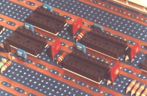
This picture shows the completed board from the component side. Not a wire in sight.
Decoupling capacitors have been added (the blue ones).
You can see: resistors, capacitors (the red ones), a semiconductor on the left and, of course, the IC sockets.
All that is now required is to fit the Integrated Circuits, the correct way round, and apply the power.
Any problems, if there are any, can be found using the normal methods of scope and meter.
Incorrect wiring can be changed by first removing solder with a solder sucker then cutting the old wire out with a scalpel. New wire is added using the pen as before. The old wire can be left in the 'loom' but I prefer to remove it. However, it does not matter. A small, good quality, pair of tweezers comes in handy for removing wire.
Once the board is up and running satisfactorily it is just a repeat of the process to create another.
The first board is the one that takes the design time. The board layout has to be done also the wiring flow chart.